


Next: Staged Injection
Up: Megasquirt III Manual
Previous: Idle Advance
Subsections
The MS3 Firmware has two algorithms for controlling boost:
- Open-Loop -
Solenoid duty comes from an 8x8 duty table (TPSxRPM).
- Closed-loop -
A Proportional-Integral-Derivative (PID) loop controls solenoid duty to match
the actual boost to the boost target. An 8x8 target table (TPSxRPM) or a 6-point
boost vs vehicle speed curve is used to figure out the boost target.
In addition to the algorithm selection, there are several other settings that must be
properly configured in order to use the boost control feature. The full boost control settings
dialog can be found below:
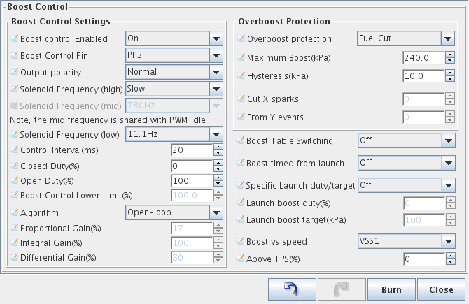
This section covers settings that are used by both the open-loop and closed-loop
control algorithms.
- Boost Control Enabled -
This controls whether the boost control feature is enabled or disabled.
- Boost Control Pin -
This sets which output pin is used to control the boost control solenoid.
Available options include:
- Output Polarity -
This is used to set the polarity of the output. Set properly, lower solenoid
duty should correspond to a more closed wastegate and yield more boost.
Available options include:
- Normal -
100% output pin duty means the wastegate is fully open.
- Inverted -
0% output pin duty means the wastegate is fully open.
- Solenoid Frequency (high) -
This setting controls the frequency range of the valve.
Available options include:
- 1.5KHz -
Operate the solenoid at 1.5KHz.
- Use Reduced -
Choosing this setting enables the Solenoid Frequency (mid)
selection (detailed below).
- Slow -
Choosing this setting enables the Solenoid Frequency (low)
selection (detailed below).
- Solenoid Frequency (mid) -
This selection is enabled when "Use Reduced" is chosen.
Available options include:
- 780Hz
- 390Hz
- 260Hz
- 195Hz
- 156Hz
- 130Hz
- 111Hz
- Solenoid Frequency (low) -
This selection is enabled when "Slow" is chosen.
Available options include:
- 78Hz
- 39Hz
- 26Hz
- 19.5Hz
- 15.6Hz
- 13Hz
- 11.1Hz
- Control Interval -
This setting is used to control how often the boost control algorithm
runs.
- Closed Duty -
This setting controls the lowest allowed solenoid duty. Normally this
should be 0%.
- Open Duty -
This setting controls the highest allowed solenoid duty. Normally this
should be 100%.
Enabling the closed-loop boost control algorithm enables the following additional
settings:
- Boost Control lower limit -
This setting controls the pressure at which the PID algorithm is enabled
and starts controlling the boost solenoid (and therefore boost pressure).
- Proportional Gain -
Proportional gain affects the strength with which changes in input immediately
affect changes in output.
- Integral Gain -
The Integral Gain setting affects the response to continued difference between
the target boost and the actual boost.
- Derivative Gain -
The Derivative Gain setting helps to slow down the response of the Proportional
and Integral gain settings as the target is reached. This should be used
sparingly as it can also completely dampen the other two Gains.
This section covers all remaining boost control settings.
Overboost protection works similarly to a rev-limiter, except that it can
stop engine operation when boost exceeds a user-set limit. In addition,
use of the overboost protection feature is required when using the
closed-loop boost control algorithm.
The following settings affect the operation of overboost protection:
- Overboost Protection -
- None -
Disables overboost protection.
- Fuel Cut -
Stops the engine by cutting fuel.
- Spark Cut -
Stops the engine by cutting spark.
- Both -
Stops the engine using both fuel and spark cut.
- Maximum Boost -
The maximum boost (in kPa) at which the engine should be operated.
- Hysteresis -
The amount boost must drop by (in kPa) after hitting the maximum
boost before fuel or spark are restored.
- Cut X sparks -
Cut this many spark events ...
- From Y events -
From this many possible spark events.
The following settings remain:
- Boost Table Switching -
This option when enabled allows a switch input to be configured which
switches between two different boost duty or target tables.
Settings include:
- Off
- Tableswitch
- PE0/JS7
- PE1
- JS10
- JS11
- JS5
- JS4
- Launch in
- Datalog in
- Boost Timed From Launch -
If launch control is enabled, this setting allows
a specific boost duty or target to be used for
a set amount of time after launch.
- Specific Launch Duty/Target -
If launch control is enabled, this setting controls
what target (closed-loop) or duty (open-loop) is used
for boost control.
- Launch Boost Duty -
This is the duty used by Specific Launch Duty/Target.
- Launch boost target -
This is the boost target used by Specific Launch Duty/Target.
- Boost vs speed -
this item enables the use of the boost vs speed curve. It has
the following options:
- Above TPS % -
This setting is used in conjunction with the Boost vs Speed function.
Below this TPS setting, the normal boost tables are used. Above
this TPS setting, the boost vs speed curve is used.
This section reviews some tips for tuning closed-loop boost control. Tuning closed-loop
boost control should be done in two steps:
- Tune open-loop boost control -
In order to make sure that you have the proper polarity set for your valve, and to
get a feel for the boost that certain duty cycles yield, it is recommended that open loop
boost control is tuned first.
- Set Up Overboost Protection -
The closed-loop boost control code uses the maximum boost set in Overboost Protection for
some of its internal calculations. This was done purposely so that during the tuning
process for boost control, if the settings wildly incorrect, boost will still not climb
any higher than the Overboost Protection allows it.
- Tune Proportional-Integral-Derivative (PID) gains -
The PID gains are the main controls for how quickly the boost will reach the target, and
how close it will remain to the target through the RPM range. Steps for tuning this
can be found below.
Open-loop boost control tuning is very simple. The main tuning table appears below:
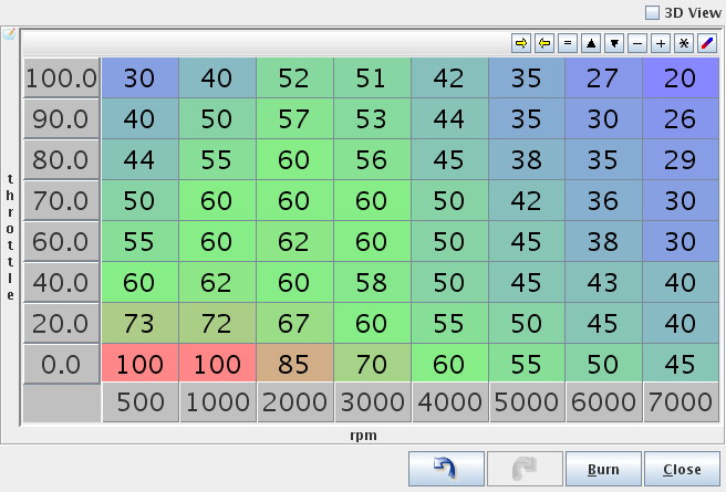
Notice that areas which should have low boost have higher duties. This is because a
higher duty should correspond with a more opened wastegate, which should correspond
roughly to lower boost. If while tuning open-loop boost, higher duty results in
higher boost and closed-loop boost control will eventually be used, toggle the
Output Polarity setting to the opposite of its current setting.
To tune the actual boost levels, just adjust the duty table so that boost reaches the
desired level at each point in the table.
Use open-loop boost control to try out different frequency settings and find the settings
that work the best for the particular solenoid being used.
The boost control settings dialog contains the Overboost Protection settings. Setting this
ups very similar to setting up a rev-limiter. Choose from Fuel Cut or Spark cut or Both. If
the engine being tuned is still equipped with a catalytic converter, spark cut should not be
used.
The maximum boost should be set up a few kPa higher than the maximum target boost will be in
the closed-loop boost target table. Hysteresis should be set so that MAP jitter does not
cause it to alternate rapidly between on and off.
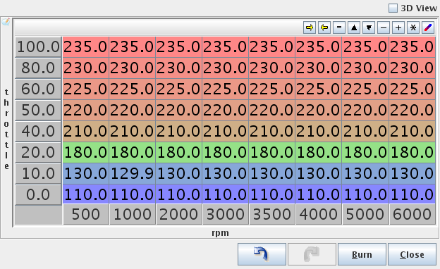
The first step for tuning Closed-loop boost control is to set the desired targets in the
Boost Control Target table. Typically lower throttle positions will have lower boost targets:
Typically, the defaults for the following settings can be used:
- Control Interval -
The default for this setting is 20 ms. This is typically a good place to start.
Lower settings can be used if overshoot cannot be tuned out when tuning the
PID parameters.
- Closed Duty -
A closed duty of 0% is the default. This should be tuned to the
value that starts to open the wastegate, but typically 0% works well.
- Open Duty -
An open duty value of 100% is the default. This should be tuned to
the value that fully opens the wastegate, but typically 100% works well.
- Boost Control Lower Limit -
This setting is used to set the pressure at which PID boost control is engaged.
The default for this setting is 100. If a faster rise to target is desired
this setting can be set to a higher number, but the safest number is 100 since
it gives the PID code the most time to react to climbing boost.
The next step after setting up the target table and supporting settings is to tune the PID gains:
- Set Integral and Differential Gains to 0% -
To make tuning the Proportional gain easier, set the Integral and Differential gains to 0%.
- Set Proportional gain to 100% and slowly lower -
While tuning Proportional gain, higher numbers mean slower boost climb and lower final boost.
For safety, start with a very high gain (100% should be sufficient). Find the RPM that
typically spools quickly, and fully and quickly depress the accelerator. Note how much boost
is reached. If boost overshoots the target dramatically, increase the Proportional gain. Otherwise, reduce
the Proportional gain and try again. Do this until boost reaches the target with a small amount of
overshoot.
- Tune the Integral Gain -
The next step after the target is reached consistently is to tune the Integral gain.
Starting from the RPM used to tune the P-gain, fully depress the accelerator and watch
the boost as the engine climbs through the RPM range. As the engine accelerates through
the rev range, the boost will probably creep away from the target. Keep increasing the I
gain until the controller adequately maintains the target with minimal oscillation. It may
be necessary to increase the P gain a bit after tuning the I gain since the two gains tend
to counteract each other.
- tune the Derivative Gain -
Increase the D gain until the overshoot is minimized. Care must be taken when increasing the D gain as too much
D gain can over-dampen the effects of the P and I gains.
Next: Staged Injection
Up: Megasquirt III Manual
Previous: Idle Advance
