


Предыдущий: Вступление
Следующий: Регулировка состава смеси (AFR/EGO Control)
Подразделы
Этот раздел содержит самые основные настройки необходимые для правильной
работы двигателя с ЭБУ MegaSquirt III.
- Подменю расчёта топлива (Required Fuel) -
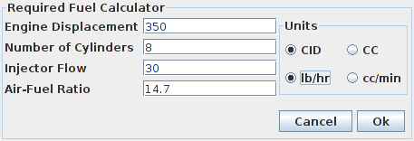
В этом подменю указываются настройки необходимые ЭБУ MS-3 для просчёта единицы количества топлива,
которым он будет оперировать в последствии при подготовке смеси.
- [Engine Displacement] -
Здесь указывается объем двигателя в кубических дюймах (CID) или
кубический сантиметрах (СС). Зависит от соответствующей
"галочки" в окне Units.
- [Number of Cylinders] -
Количество цилиндров.
Для роторных двигателей Ванкеля с двумя роторами укажите 4,
с тремя роторами - 6, с четырьмя - 8 и т.д.
- [Injector Flow] -
Здесь указывается номинальная производительность используемых топливных форсунок,
в фунтах за час (lb/hr) или кубический сантиметрах в минуту (CC/min).
Зависит от соответствующей «галочки» в окне Units.
- [Air-Fuel Ratio] -
Желаемое воздушно-топливное отношение (AFR) горючей смеси.
Чаще всего берут стехиометрическое отношение
(14.7:1 для бензина), которое подразумевает наилучшее
сгорание топлива.
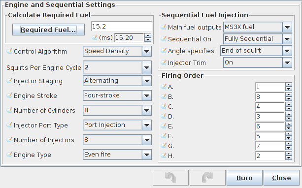
- [Control Algorithm] -
определяет метод расчёта нагрузки на двигатель в ЭБУ MS-3.
Он может быть основан на замере давления внутри впускного коллектора,
на положении дроссельной заслонки, на объёме расходуемого воздуха или
на комбинации нескольких из перечисленных способов.
Note that this setting only sets the control
algorithm for fuel injection and related settings; it does not set the
control algorithm for ignition and related settings.
The following settings may be selected:
- [Speed Density] -
Use the MAP (Manifold Absolute Pressure) sensor to determine load.
In this case, the vertical axis of any fuel table lookups is in
kilopascals (kPa). The maximum value reported by the MAP sensor
(in non-turbo applications) will be the same as the barometric
pressure.
- [Percent Baro] -
This setting is similar to the Speed Density setting in that the
MAP sensor is used to determine load. However, instead of directly
using the manifold pressure, the manifold pressure is divided by
barometric pressure to give a percentage of barometric pressure.
This setting can be useful for those who regularly drive at high
altitudes. It ensures that regardless of barometric pressure, all
table lookups operate over 0-100%.
For example, if barometric pressure is 80 kPa, and the engine is
operating at 50 kPa, the actual value used for table lookups is
50kPa/80kPa or 62.5%.
- [Alpha-N] -
Use the throttle position to determine load on the engine. Be sure
to calibrate the throttle range using Tools->Calibrate TPS
before using this setting.
- [MAFMAP] -
This setting is for users who are using a Mass Airflow sensor,
but want to tune using the standard VE table. It calculates MAP
based on the engine size, RPM, and other parameters. This calculated
MAP is then used for fuel-based table lookups.
- [MAF] -
Use the MAF sensor and related calculations to directly determine
the amount of fuel to inject. In this mode, the VE table is not
used to determine the amount of fuel to inject. More information
on this load mode is in another dialog's description.
- [ITB] -
This mode was created specifically for naturally aspirated engines
running with independent throttle bodies. It combines alpha-n (at
high engine loads) with speed density (at low engine loads), using
the load calculation that makes the most sense at each RPM. For
example, most ITB setups do not have good vacuum at idle or low
RPM, and slightly touching the throttle makes them lose all vacuum,
but at higher RPM start to respond more like a traditional single
throttle body engine. This mode allows the use of speed density at
low engine loads and switches to alpha-n at high loads, with an
adjustable switchpoint curve over RPM (detailed in another section).
- [Squirts Per Engine Cycle] -
Determines the number of times per engine cycle (two revolutions on a
four-stroke engine) injectors are squirted when in a batch injection mode.
This setting has no effect when injecting sequentially.
- [Injector Staging] -
This setting is used only in batch injection modes. It determines whether
the two injection channels are squirted at the same time, or in an
alternating fashion.
- [Engine Stroke] -
Sets the firmware for either a four-stroke engine or a two-stroke engine.
- [Number of Cylinders] -
Sets the number of cylinders for the engine. Note that fully sequential
injection is only possible with up to 8 cylinders.
- [Injector Port Type] -
This setting is not used by the firmware and is included for historical
purposes.
- [Number of Injectors] -
Determine the number of injectors installed on the engine. Fully sequential
injection is only possible with up to 8 cylinders and 8 injectors. When
used with the staged injection feature, this should be set to the number
of primary injectors.
- [Engine Type] -
Determines whether the engine is an even-fire engine or odd-fire engine. An
even fire engine is an engine where the crankshaft moves an equal number of
degrees between each cylinder's top dead center (TDC). An odd fire engine
may have a different number of degrees between TDC on some cylinders when
compared with others.
Sequential Fuel Injection settings follow:
- Main fuel outputs -
- [Std fuel] -
Use the standard v3/3.57 board batch injector outputs.
- [MS3X fuel] -
Use the MS3X expansion board's outputs to drive the
fuel injectors. Only one injector should be used per
output.
- Sequential On -
- [Off] -
Use batch injection. On MS3x outputs, the channels are divided
into two groups, and all injectors in a group are squirted
simultaneously.
- [Semi-Sequential] -
Use batch injection, but allow the angle of injection to be
specified. When used with the MS3X injector outputs, injectors
should be wired in the same manner they would be wired for
fully sequential injection.
- [Fully Sequential] -
Use fully sequential injection. In this mode, outputs A-H are
squirted in sequence, so care must be taken to use the correct
wiring for the engine's fireing order. For example, for a four
cylinder engine with firing order 1-3-4-2, the following wiring
should be used:
- Output A - Cylinder 1
- Output B - Cylinder 3
- Output C - Cylinder 4
- Output D - Cylinder 2
- Angle Specifies -
- End of Squirt -
The angle specified in the injector timing table specifies the angle
of the end of each squirt. This should be used by most people
for most engines.
- Middle of Squirt -
The angle specified in the injector timing table specifies the angle
of the middle of each squirt.
- Beginning of Squirt -
The angle specified in the injector timing table specifies the
angle of the beginning of each squirt.
- Injector Trim -
- Off -
Per-injector fuel trim is disabled. All injectors will have the same
pulse-width.
- On -
Per-injector fuel trim is enabled. Each injector's pulse-width can be
trimmed lower or higher than the value calculated using the fuel
equation.
Firing order:
The firing order should be set to the firing order that your engine uses. It does
not affect the order in which the outputs are triggered. Instead it is used to
associate an injector trim table with a particular physical output so that
when injector trim is applied, it is applied to the correct cylinder. It is also
used if closed-loop EGO is being done per-cylinder.
Предыдущий: Вступление
Следующий: Регулировка состава смеси (AFR/EGO Control)
