


Следующий: Idle Advance
В начало: Содержание
Предыдущий: Контроль состава горючей смеси (AFR/EGO)
Подразделы
The MS3 firmware has several methods for controlling idle speed:
- On/Off Valve -
This Is for controlling a simple on/off valve.
- Warmup-only modes
These modes are open-loop and only control valve position based on
coolant temperature.
- IAC Stepper Always On -
Leave IAC stepper power on even when not moving.
- IAC Stepper Moving Only -
Power up IAC stepper motor only when necessary for moving.
- PWM Warmup -
PWM valve in warmup only mode.
- 15-minute IAC -
Power up the IAC for 15 minutes for warmup, then power it
down.
- Closed-loop modes
These modes are closed-loop. The user must set a target RPM curve,
and several other settings to determine when the code goes into
closed loop mode.
- PWM Closed Loop -
PWM idle valve in closed loop mode.
- IAC Closed Loop Moving Only -
Closed loop IAC mode where the IAC motor is only turned on
when the valve needs to move.
- IAC Closed Loop Always On -
Closed loop IAC mode where the IAC motor is on whether the
valve needs to move or not.
Each mode is described in detail below.
The On/Off Valve idle speed control option is the most simple control option
included in the MS3 Firmware. It includes the following settings:
- Fast Idle Temperature -
This is the temperature below which the idle valve is turned on.
- Port -
This is the output port to which the idle valve is connected.
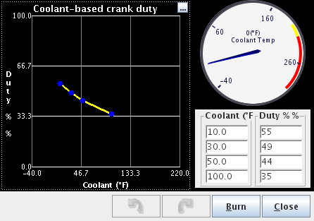
The only common settings between Warmup-only and Closed-loop control methods are the
cranking position curves. That curve sets the position of the PWM controlled idle valve
during cranking, depending on the coolant temperature (PWM idle has nothing to do with
cranking fuel pulsewidth):
All PWM-based modes have certain settings which are shared:
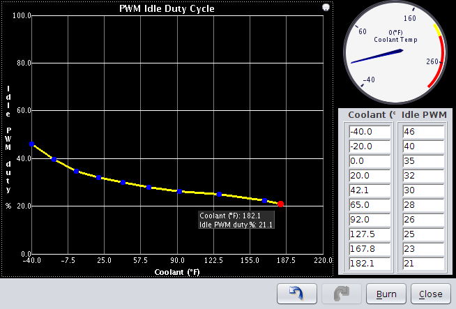
The Warmup Only options are open-loop modes that set the IAC/PWM valve to a specific position
based on the Coolant temperature. The user must set each temperature and a corresponding
valve position in a curve:
All warmup-only modes also have the following common setting:
- Crank-to-Run Taper Time -
Time in seconds to go from the crank position to the run position.
The four warmup-only output options are detailed below.
The IAC Stepper modes all have several common settings. Those settings are detailed here.
- Time Step Size -
This is the number of milliseconds the firmware will wait between each step.
If a valve does not move reliably, this setting should be increased.
- Minimum # of steps to move -
This is the minimum number of steps the controlling piece of code has to command
before the code that moves the valve will actually try to move the valve.
- Start Value -
This is the number of steps the valve will move (in the closing direction) on boot
so that the rest of the code can rely on the start position being accurate.
IAC Warmup Moving Only is an open-loop algorithm which sets the valve position based directly
on coolant temperature. Keep in mind that this mode turns off the valve between each set of steps.
If the valve does not work reliably in this setting, it may be necessary to use the Always On setting.
In addition to the common IAC motor settings, this mode also has the following setting:
- Initial Time Step Size -
This is the number of milliseconds the firmware will wait after turning on
the idle valve before trying to move the pintle.
This mode is exactly the same as IAC Warmup Moving only, but does not have the Initial Time
Step Size setting since it leaves the valve turned on all the time.
This mode is exactly the same as the other IAC Warmup modes, but leaves the valve on for 15 minutes
after start, then turns it off.
This mode works functionally the same as the IAC Warmup options, but for a PWM valve
instead.
The MS3 firmware employs a PID (Proportional Integral Derivative) method of control for
controlling idle speed to meet the user-specified target RPM. Target RPM is specified in a
Coolant-temperature-based curve. Common settings for all closed-loop modes as well as options
specific to each type of valve are listed below.
A curve for setting the target RPMs based on coolant temperature is used by all
closed loop idle-speed control modes. All other idle-speed control settings are listed as well:
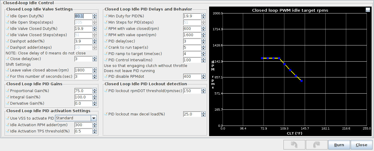
Settings common between all modes are listed here:
This setting applies the above settings to a PWM Idle valve.
This setting applies the above settings to an IAC motor. In this mode the motor will
only be turned on when it is commanded to move. The IAC motor common settings from the
warmup-only section apply here as well.
This setting applies the above settings to an IAC motor. In this mode the motor will
be on as long as the MS3 has power. Use this setting if Moving Only gives unreliable results.
The IAC motor common settings from the warmup-only section apply here as well.
Before trying to tune closed loop idle speed control, be sure to try tuning warmup only
idle speed control. With warmup only control, a higher step-count or duty should yield
higher RPM. Make sure that this is the case, and that smooth idle speed can be attained
with warmup only before moving on to closed loop control.
There are two main things to tune when tuning closed-loop idle speed control:
- PID gains
- Conditions for entering PID control
It is recommended that tuning is done in stages. For example, PID cannot be tuned if
the code is never entering the PID loop. Because of this it is a good idea to start by tuning
the conditions for entering PID control.
These settings include:
- Use VSS to activate PID -
This takes the place of the PID lockout settings. Turning this on
will make it so that the PID loop activates after the vehicle speed
comes to zero MPH/KPH.
- Idle activation RPM adder -
Set to 200-300 RPM for best algorithm performance.
- Idle Activation TPS threshold -
Set as low as possible. If the TPS has a bit of noise, set it to around 1%,
otherwise set it to 0.3%-0.5%.
- PID delay -
This should be set so that the RPM dropping on throttle lift can come to a rest
slightly higher than the target RPM, and become stable there. Between three and five
seconds normally works the best.
- Crank to Run Taper -
This setting controls how long after starting the code will delay before entering PID. Between three and five
seconds works well for this setting.
- PID lockout rpmDOT threshold -
This is the first of the PID lockout detection settings. Use this setting so that
the code can tell the difference between decelerating with closed throttle (engine braking)
and sitting at one RPM. Set this as low as possible without being below what is normal
rpmDOT jitter with the engine RPM not changing. Typical values will be between 50 and 75 RPM/sec.
- PID lockout max decel load -
This is the second PID lockout detection setting. The code assumes that if MAP is lower than
this setting, the driver must be decelerating, and not "locked out" of the PID loop. Set this
to a value just under the load seen with an idle slightly higher than the current target RPM +
the Idle Activation RPM Adder. This can be done by temporarily switching to warmup-only mode or
idle test mode, and setting the valve position manually.
- PID disable RPMdot -
A good value for this setting will typically be in the 200-400 RPM/sec range. If the engine speed
suddenly accelerates with no throttle input (like if the clutch is engaged while the car is rolling
and in gear), it must accelerate at a rate greater than this setting before the PID code will be
disengaged. Setting this value too high can lead to stalls after engaging the clutch in this manner.
To tell whether the code is entering PID idle control, the "CL Idle" indicator in TunerStudio must be used. If
the current gauge cluster in TunerStudio does not include this indicator, temporarily switch to a cluster
that does.
Most modern OEM cars enter idle speed regulation in a very similar manner. The MS3 idle speed control
algorithm was designed to emulate this behavior. The sequence of events that the code was designed
to follow are listed below:
- Throttle Lift -
On throttle lift, the code opens the valve to the value learned in the last iteration of the
PID loop + the dashpot adder. The logic here is that the last learned value should result in an
RPM close to the target RPM. The dashpot adder is added so that when RPM settles, it settles
to an RPM slightly higher than the target. This is in case the air conditioning was turned on
or IAT increased or anything else that might make RPM lower than the last time the PID code
ran.
- RPM settles -
After throttle lift, eventually the clutch is pushed in and RPM drops to wherever it will settle
given the learned value + the dashpot adder. Hopefully the idle has settled to an RPM that is
less than the commanded target + the Idle Activation RPM adder. IF so, then the code will wait
for the amount of time specified by the PID delay, and then enter PID control. If RPM settles
above the commanded target + Idle Activation RPM adder, the code then starts checking the PID
lockout detection conditions. Assuming those condtions are met, the code will still enter the
PID loop after the amount of time specified by the PID delay.
- PID control activates, RPM starts dropping to target -
After the PID delay expires, the PID code will be activated. RPM will slowly drop to the target
over the number of seconds specified by the PID ramp to target time.
- Normal idle speed reached -
RPM reaches the commanded target. PID continues regulating RPM until the throttle is pressed.
Once the code is reliably entering PID on every throttle lift, it is time to actually tune the PID code
to reach and hold the RPM target.
The settings that are associated with or affect the operation of the PID algorithm are listed below:
- Idle Open Duty/steps and Idle Valve closed duty/steps -
These should be set to the minimum and maximum values that should be used during PID loop
and driving operation. In addition, having these set further apart results in the PID loop being more
sensitive (making changes to the output given much smaller changes in input).
- Min duty/steps for PID -
This is the lowest duty/number of steps that the PID loop is allowed to command. Set this low
enough to result in an RPM slightly lower than the lowest target RPM.
- RPM with valve open/closed -
These should be set to the RPM with the valve closed and the RPM with the valve opened respectively.
If using these settings makes the code unresponsive to changes in idle speed, the upper RPM value
can be set lower.
- PID Control Interval -
This controls how often the PID code runs. Setting this too high can result in sluggish response to
sudden changes in load, such as the Air Conditioning being turned on. Setting it too low can
result in the loop being overly sensitive to RPM changes. Typically 100ms works well.
- PID controller gains -
These control the actual response of the code to changes in RPM, as well as how well the code will
reach the target. Tips for tuning these are listed below.
The following basic steps should be used for tuning the PID controller gains:
- Zero all the gains -
Set all the gains to 0%. This is so that the effects of tuning the I-term in the next step are not
confused with the effects of any other setting.
- Tune the Integral (I) gain -
The Integral gain is the only term that controls whether the code actually reaches its target.
Higher values for Integral gain will result in the code being able to get closer to the commanded
target; however, a value that is too high will result in oscillation. The easiest way to determine
a good value for the I term is to keep increasing it until oscillation occurs, then slightly lower
it. If this value is increased to 200% without reaching a point where oscillation occurs,
then the RPM with valve opened setting can be decreased as far as necessary, and the open duty/steps
setting and closed duty/steps setting can be made further apart to make the PID loop more sensitive.
- Tune the Proportional (P) gain -
After tuning the I gain so that the RPM reaches the commanded target without oscillation, the P gain
can be tuned. The best way to tune this is to set it as high as possible without getting any
oscillation. After setting this, try turning on the air conditioning or other accessories that
normally lower RPM or increase load. When these accessories are turned on, the RPM should dip a bit
then recover (the valve position should increase significantly). Using longer PID ramp to target times
can also make it so that when the PID algorithm engages, a higher P gain can be set without causing
oscillation.
- Tune the Derivative (D) gain -
For most users, use of the D gain should not be necessary. It substantially dampens the response
of the loop.
Some final tips:
- Idle Fuel Tuning -
Before even attempting to tune Closed-loop Idle speed control, tune the area around idle so that
if RPM goes up or down or load goes up or down, the AFR stays close to the same value. Changing
AFR can affect idle speed, which can then cause the PID code to try to correct, getting into
an unrecoverable oscillation.
- Idle Advance -
The idle advance feature can be used to help "catch" the idle in situations where heavy load
is suddenly added while the engine is idling. It is recommended that the advance is increased with
increasing load, and decreased with decreasing load. This way when the air conditioning or
electric fan are turned on, the sudden increase in load causes a corresponding increase in timing
which generates more power. Also, this feature can be used so that on idle without load, slightly less
than what would normally be considered "optimal" timing can be used. This causes the idle valve
to need to open further to keep a particular idle speed. Then when sudden load is added, the timing
increases and the valve position does not have to change as much to cope with the sudden load increase.
Следующий: Idle Advance
В начало: Содержание
Предыдущий: Контроль состава горючей смеси (AFR/EGO)
